A title block that calls for +/-0.002" on all machined features is a tolerance that a well-maintained manual mill with an experienced operator can often meet on the critical dimensions. Whether it can meet it consistently, on every feature, across multiple parts, is a different question.
Tolerance on a manual machine is not a single number. It is an outcome that depends on machine condition, fixturing, measurement practice, material behavior, and how much the operator knows about the specific job.
What the machine is actually working with
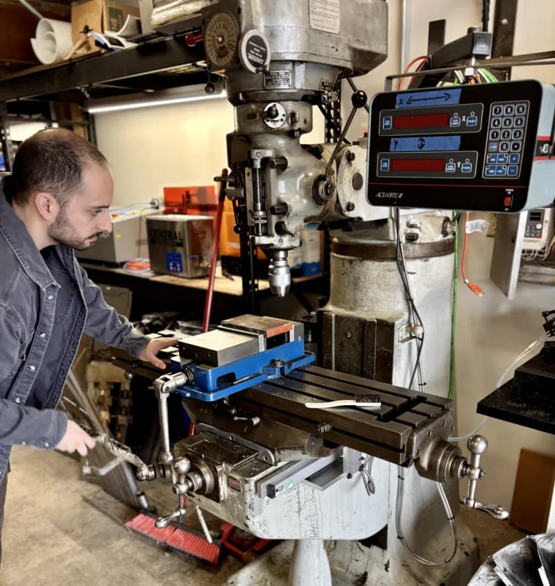
A manual mill moves the table by turning a leadscrew. On a worn machine, there is backlash in that leadscrew. The dial reads 0.500" of travel but the table may have moved 0.515" because the leadscrew nut has some clearance worn into it. An experienced operator knows their machine's backlash and compensates by always approaching a target position from the same direction. That works until the job requires approaching from different directions, or until someone is moving quickly and not paying close attention.
A digital readout changes this substantially. A manual mill with a DRO reads table position directly from a linear encoder rather than from the leadscrew dial. The DRO knows where the table actually is, not where the leadscrew thinks it is. A shop with a DRO can hold position more consistently than the same shop without one. If tolerances matter on a manual job, it is worth asking whether the shop has a DRO before the job goes out.
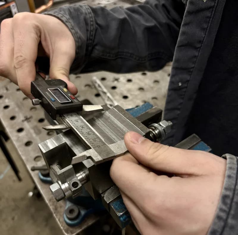
Fixturing matters too. A part that shifts during a cut is going to be out of tolerance. One that is held solidly in a vise or on a fixture plate will hold better than the same part clamped to the table in a way that allows any movement.
Temperature is real at tight tolerances. A steel part that heats up during the day will expand. A 10-inch piece of steel expands roughly 0.0006" per degree Fahrenheit. In a shop that swings from 55 degrees in the morning to 75 degrees by afternoon, that is 0.012" of thermal growth on a 10-inch part. For most work that is irrelevant. For a part with +/-0.001" tolerances across a long dimension, it is not.
What a manual mill can typically hold
| Feature | Without DRO | With DRO |
|---|---|---|
| Linear dimensions | +/-0.003" to +/-0.010" | +/-0.002" to +/-0.005" |
| Hole location | +/-0.005" to +/-0.015" | +/-0.002" to +/-0.005" |
| Hole size (end mill) | +/-0.003" to +/-0.005" | +/-0.002" to +/-0.003" |
| Hole size (reamed) | +/-0.0005" | +/-0.0005" |
| Step heights | +/-0.002" to +/-0.005" | +/-0.001" to +/-0.003" |
These are general ranges for a well-maintained machine with a skilled operator. A machine that is not well-maintained will do worse. A particularly careful setup on a single critical dimension can sometimes do better.
Reaming is the outlier in this table: the reamer controls the bore diameter, so the achievable tolerance on a reamed hole is much tighter than what the mill alone can hold on an end-milled bore. If you need a precise bore on a manual job, specify reaming.
Why drawings often ask for more than they need
Tolerances get copied from drawing to drawing. An engineer starts a new part from a previous similar drawing, and the title block tolerance from that drawing comes along for the ride. If the previous drawing was for CNC work, the tolerances it called out may have been appropriate for that context but are tighter than the current part actually requires.
There is also a general tendency to err toward tight when the functional requirement is ambiguous. If an engineer is not sure whether a bore needs to be +/-0.003" or +/-0.010", specifying +/-0.003" feels safer. In practice, it may just mean more setups and higher cost for a part that would have worked fine at the looser tolerance.
This is not a criticism of the engineering process. It is a feature of how drawings get made. The fix is to look at the functional requirement for each critical feature and set the tolerance based on what the assembly actually needs, not on what the last drawing happened to call for.
When to move to CNC
Manual machining makes sense for one-offs and short runs where the part geometry is not too complex and the tolerances are within the ranges above. CNC starts to make more sense when the job requires consistent tolerances across multiple parts, when geometric tolerances (parallelism, perpendicularity, true position) need to be held tightly, or when the drawing routinely calls for +/-0.001" or tighter on multiple features.
A manual operator can hit +/-0.001" on a good day on a single critical dimension. A CNC machine can hold it on every part across a 50-piece run without the operator having to think about it. For production work, that consistency matters more than any single-part capability.
Call the shop before you finalize the print
A conversation before the drawing is final can save time on both ends. If the part is going to a manual shop, understanding what that shop's machine can actually hold, and whether the tolerances on the drawing are tighter than the part needs, is worth a short conversation.
Most shops will tell you straight whether a tolerance is achievable or not. The ones worth working with will say so before the job starts, not after the first part is scrapped.
Tolerances you can rely on
If you have a part with tight tolerances and you are not sure whether a manual shop is the right fit, reach out before the drawing is final. Arinta Engineering does custom machining, fabrication, and CAD design out of Sturtevant, Wisconsin, available evenings and weekends. A quick conversation before the print is locked is usually worth it.
Get a Quote